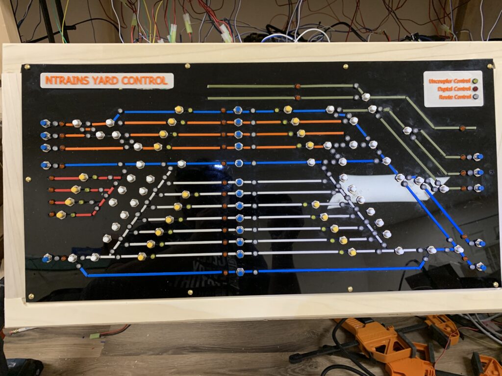
In this era of DCC the role of an analog control panel seems like a real indulgence. It is hard however to give up on the tactile pleasure of clicking buttons and visual indicators for setting switches and routes. I embarked on the creation of a control panel for the Yard to be able to perform the following functions:
- Display the tracks, sidings, stubs and fiddles of the yard visually.
- Allow for push button setting of switches
- Indicate the position of various switches
- Allow route selection by pressing a combination of routing buttons
- In a somewhat ‘not-prototypical’ function allow for operating e-m uncouplers on the tracks
- Finally occupancy detection indicators on all the key sections of the yard.
Control Panel Display
The control panel was milled from a sheet of acrylic

After milling push-button switches were installed and inlays made with 3D printed colored track markers were glued into the channels to distinguish the classification yard from the passenger yard and service areas as well as bypass tracks.
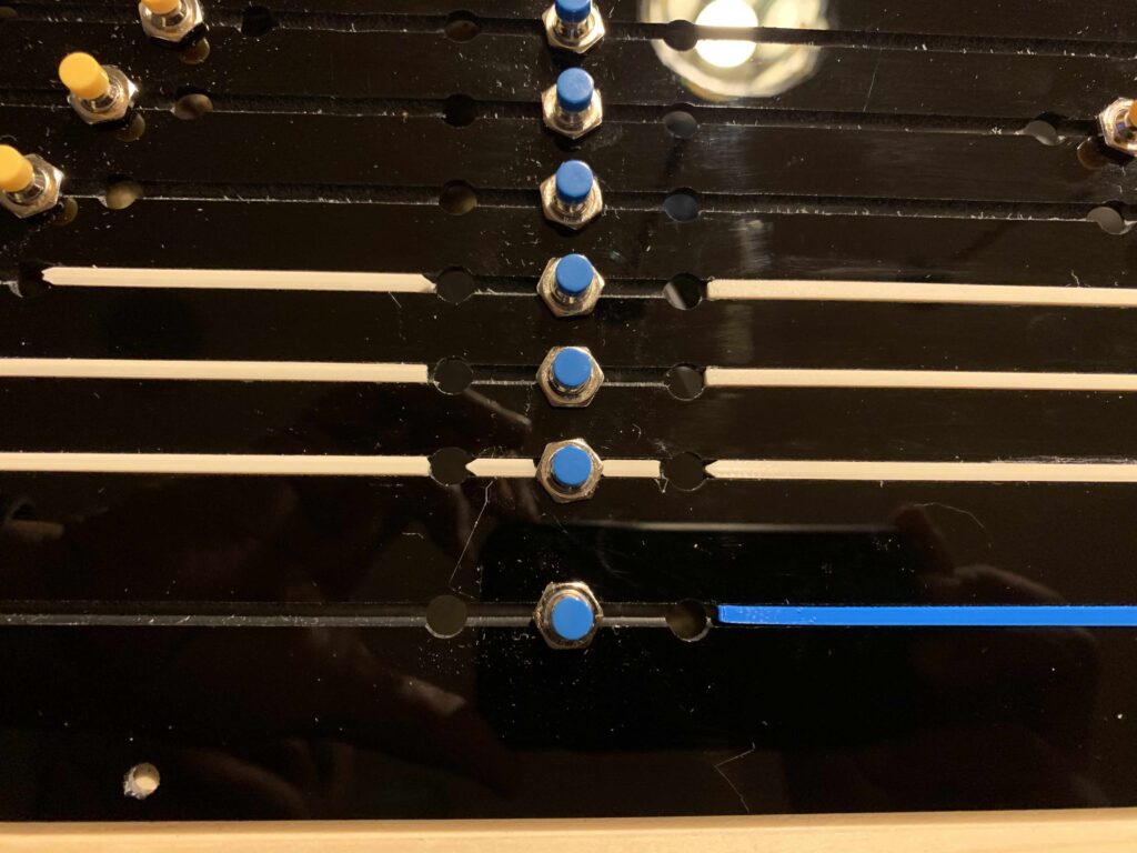
The finished panel was then mounted on the wooden frame of a hinged box that was designed to contain the electronics.

Switching Kato Switches with Panel Push Buttons
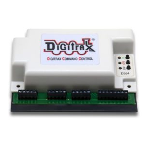
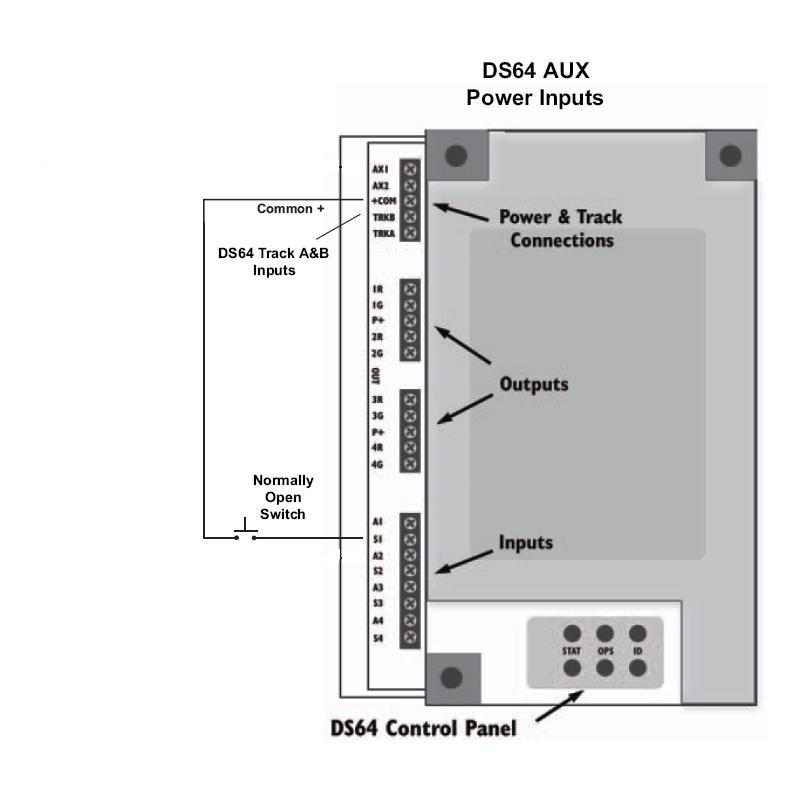
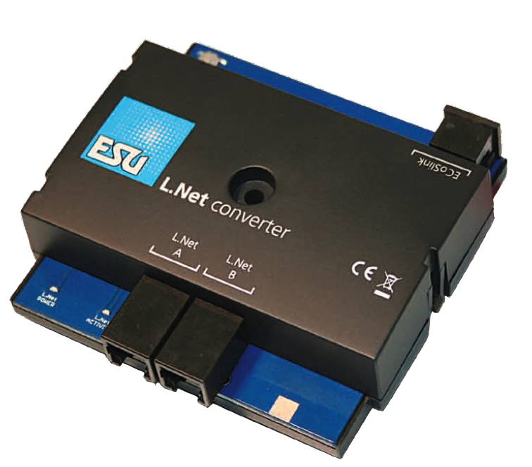
As much as I like the ESU Switch Pilot and can drive Kato Switches in combination with the Switch Pilot Extension there is no way to drive these locally except through the use of an ECoS Detector, I found the simpler (less expensive) solution was to use the Digitrax DS64 which not only drives the Kato switches directly but also has a button actuator connection. The only additional requirement is an LNet Converter from ESU to connect the DS64s to the ECoS and then any local switching is also reflected on the ECoS control.
Integrating Loconet feedback from DS64 into ECoS
This task has been made very easy by the LNet Converter from ESU. This allows parsing of Loconet messages to and fro ECoS and allows interoperability of the RailCom feedback from ESU SwitchPilots on the layout and the DS64s. Additionally local button push feedback is sent to the DCC keeping the system in sync.
Driving Bi-color LEDs to Display Switch Positions with an ECoS Detector Extension.
I needed to use bicolor green/red LEDs on my control panel to indicate which track was selected by a given turnout(switch) to save space and reduce the number of LEDs to 2 per turnout (there will be 43 turnouts on the panel). Unfortunately the ECos Detector Manual is not helpful for this – but the description of the outputs per the ESU website is as follows :”Each one of the 32 outputs provides current up to 100mA max. Since these outputs are conducted as ‘open collectors’, you are able to connect either small light bulbs or LEDs with current limiting resistor directly to it. “
So the logical thing to do was to take off the cover from the detector an get a clue to its architecture. The board is driven by a microprocessor which then leads to 4 shift registers that drive 8 N channel MOSFETS which act as open drain outputs.

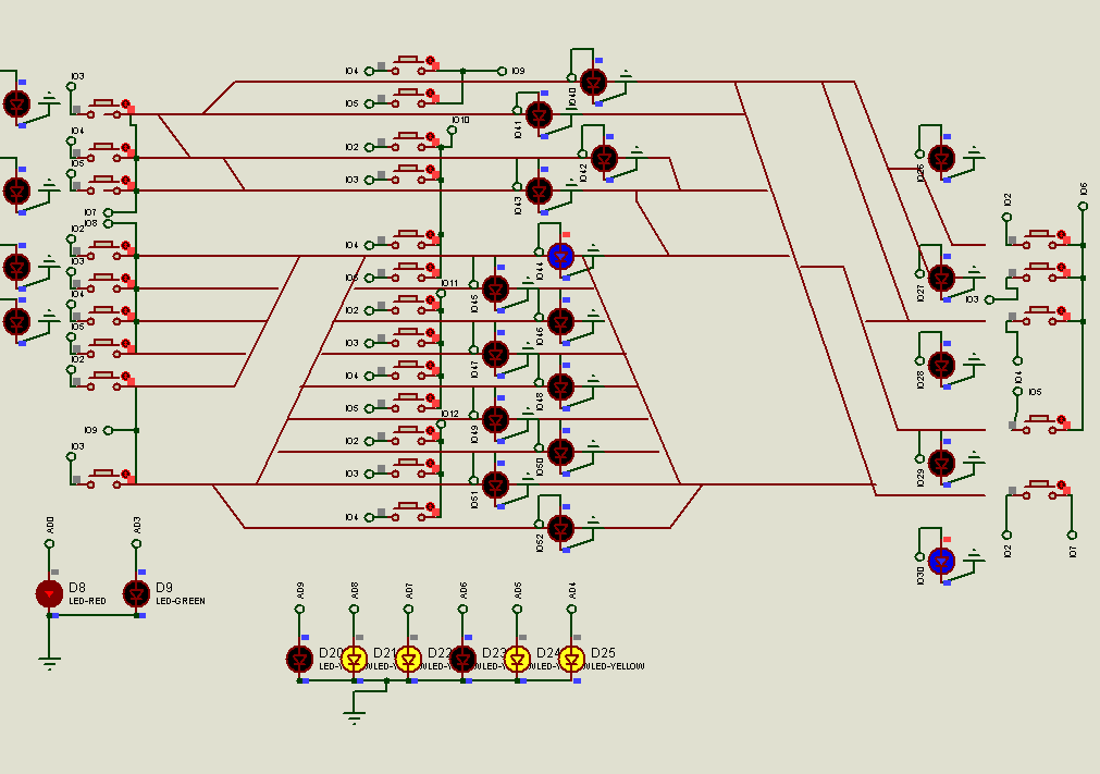
So it is possible to connect two outputs to the U+ terminal via 10K resistors and then bridging a bicolor LED across the two outputs (of course with the appropriate resistor to drop the voltage from 12V to the typical 2.2 Volts tolerated by the LED). I used the bicolor LED L10008-ND for my application. Below is a simulation of the circuit in Proteus VSM. Here there two pairs of bicolor LEDs are connected in revered polarities for use on the control panel. Thus when one route is selected the respective LED turns green and the other red. The switch is mimicking the shift register outputs being reciprocally switched by the detector.
Route Selection
I wanted to be able to define a route through the yard by pressing a button corresponding to the entry, chosen track to pass and exit from the yard. Basically three blue push buttons on my panel.
ECoS allows routes to be selected in response to a button press or for that matter several buttons pressed together but that would be quite a feat even on a small panel. Furthermore there are nearly 35 different combinations which would cost a fortune in ECoS detectors! So I needed a better solution. Interestingly the ECoS system will trigger a route based on upto 8 conditions. If each of those 8 is a switch then we have 28 combinations ie. 256 combinations. So off i went to the programming board to create a program that would accept a combination of 3 buttons to yield a unique binary call to just 8 inputs on a detector and create a route condition. Let me spell this out.
If you look at the yard layout:
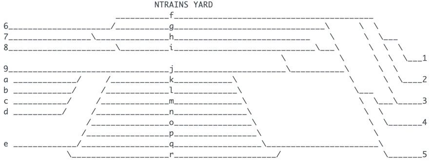
Now every route is simply a three character combination. The blue buttons while physically laid out to match the layout are wired to make a 28 key keypad.
The Schematic
The Code
//ntrains.org
//Route controller
//By pressing a combination of three panel buttons the appropriate route is trigerred via
//the ESU ECos detector


#include <Wire.h>;
#include <Keypad.h>;
#include <EEPROM.h>;

const byte numRows= 7; //number of rows on the keypad
const byte numCols= 4; //number of columns on the keypad

//keymap defines the key pressed according to the row and columns just as appears on the keypad
char keymap[numRows][numCols]=
{
{'1', '2', '3', '4'},
{'5', '6', '7', '8'},
{'9', 'a', 'b', 'c'},
{'d', 'e', 'f', 'g'},
{'h', 'i', 'j', 'k'},
{'l', 'm', 'n', 'o'},
{'p', 'q', 'r', 's'},
};

//Code that shows the the keypad connections to the arduino terminals
byte rowPins[numRows] = {6,7,8,9,10,11,12}; //Rows 0 to 3
byte colPins[numCols]= {2,3,4,5}; //Columns 0 to 3

//initializes an instance of the Keypad class
Keypad myKeypad= Keypad(makeKeymap(keymap), rowPins, colPins, numRows, numCols);

void checkEntered1(char button);
char entered[4]; //create a new empty array for the code entered by
                //the user (has 4 elements)//the user (has 4 elements)
char compare[3];


// define route strings in PROGMEM
const char string_0[] PROGMEM = "zzz";
const char string_1[] PROGMEM = "6f1";
const char string_2[] PROGMEM = "6f2";
const char string_3[] PROGMEM = "6f3";
const char string_4[] PROGMEM = "6g3";
const char string_5[] PROGMEM = "6g4";
const char string_6[] PROGMEM = "6g5";
const char string_7[] PROGMEM = "6h3";
const char string_8[] PROGMEM = "6h4";
const char string_9[] PROGMEM = "6h5";
const char string_10[] PROGMEM = "6i3";
const char string_11[] PROGMEM = "6i4";
const char string_12[] PROGMEM = "6i5";
const char string_13[] PROGMEM = "7h3";
const char string_14[] PROGMEM = "7h4";
const char string_15[] PROGMEM = "7h5";
const char string_16[] PROGMEM = "7i3";
const char string_17[] PROGMEM = "7i4";
const char string_18[] PROGMEM = "7i5";
const char string_19[] PROGMEM = "8i3";
const char string_20[] PROGMEM = "8i4";
const char string_21[] PROGMEM = "8i5";
const char string_22[] PROGMEM = "9j3";
const char string_23[] PROGMEM = "9j4";
const char string_24[] PROGMEM = "9j5";
const char string_25[] PROGMEM = "ej3";
const char string_26[] PROGMEM = "ej4";
const char string_27[] PROGMEM = "ej5";
const char string_28[] PROGMEM = "ek5";
const char string_29[] PROGMEM = "el5";
const char string_30[] PROGMEM = "em5";
const char string_31[] PROGMEM = "en5";
const char string_32[] PROGMEM = "es5";
const char string_33[] PROGMEM = "ep5";
const char string_34[] PROGMEM = "eq5";
const char string_35[] PROGMEM = "eo5";
const char string_36[] PROGMEM = "er5";
// define a route string table array of strings in PROGMEM
const char* const string_table[] PROGMEM = {
  string_0,
  string_1,
  string_2,
  string_3,
  string_4,
  string_5,
  string_6,
  string_7,
  string_8,
  string_9,
  string_10,
  string_11,
  string_12,
  string_13,
  string_14,
  string_15,
  string_16,
  string_17,
  string_18,
  string_19,
  string_20,
  string_21,
  string_22,
  string_23,
  string_24,
  string_25,
  string_26,
  string_27,
  string_28,
  string_29,
  string_30,
  string_31,
  string_32,
  string_33,
  string_34,
  string_35,
  string_36
};

#define STRINGTABLESIZE (sizeof(string_table)/sizeof(string_table[0]))
int findStringIndex(char* str)
{
  for (int i=0;i<STRINGTABLESIZE;i++)
  {
    if (strcmp_P(str, (const char*)pgm_read_word(&(string_table[i])))==0) return i; // found
  }
  return -1; // not found
}
// define button marker LEDs in PROGMEM

const char indicator_1[] PROGMEM = "a1";
const char indicator_2[] PROGMEM = "a2";
const char indicator_3[] PROGMEM = "a3";
const char indicator_4[] PROGMEM = "a4";
const char indicator_5[] PROGMEM = "a5";
const char indicator_6[] PROGMEM = "a6";
const char indicator_7[] PROGMEM = "a7";
const char indicator_8[] PROGMEM = "a8";
const char indicator_9[] PROGMEM = "a9";
const char indicator_a[] PROGMEM = "aa";
const char indicator_b[] PROGMEM = "ab";
const char indicator_c[] PROGMEM = "ac";
const char indicator_d[] PROGMEM = "ad";
const char indicator_e[] PROGMEM = "ae";
const char indicator_f[] PROGMEM = "af";
const char indicator_g[] PROGMEM = "ag";
const char indicator_h[] PROGMEM = "ah";
const char indicator_i[] PROGMEM = "ai";
const char indicator_j[] PROGMEM = "aj";
const char indicator_k[] PROGMEM = "ak";
const char indicator_l[] PROGMEM = "al";
const char indicator_m[] PROGMEM = "am";
const char indicator_n[] PROGMEM = "an";
const char indicator_o[] PROGMEM = "ao";
const char indicator_p[] PROGMEM = "ap";
const char indicator_q[] PROGMEM = "aq";
const char indicator_r[] PROGMEM = "ar";
const char indicator_s[] PROGMEM = "as";


// define an indicator string table array of strings in PROGMEM
const char* const indicator_table[] PROGMEM = {
  indicator_1,
  indicator_2,
  indicator_3,
  indicator_4,
  indicator_5,
  indicator_6,
  indicator_7,
  indicator_8,
  indicator_9,
  indicator_a,
  indicator_b,
  indicator_c,
  indicator_d,
  indicator_e,
  indicator_f,
  indicator_g,
  indicator_h,
  indicator_i,
  indicator_j,
  indicator_k,
  indicator_l,
  indicator_m,
  indicator_n,
  indicator_o,
  indicator_p,
  indicator_q,
  indicator_r,
  indicator_s
};
#define INDICATORTABLESIZE (sizeof(indicator_table)/sizeof(indicator_table[0]))
int findIndicatorIndex(char* ind)
{
  for (int j=0;j<INDICATORTABLESIZE;j++)
  {
    if (strcmp_P(ind, (const char*)pgm_read_word(&(indicator_table[j])))==0) return j; // found
  }
  return -1; // not found
}


int indicatorPins[] = {26,27,28,29,30,31,32,33,34,35,36,37,38,39,40,41,42,43,44,45,46,47,48,49,50,51,52,53};
#define kBits sizeof(indicatorPins)/sizeof(indicatorPins[0])    //number of bits
int ledPins[] = {A4, A5, A6, A7, A8, A9, A10, A12}; //least-significant to most-significant bit
#define nBits sizeof(ledPins)/sizeof(ledPins[0])    //number of bits
const int Red = A0; //red LED is on pin A0
const int greenLed = A1; //green LED is A1
const int blueLed = A3; //blue LED is A3
const int pressLed = A2;//marks keypress

int foundIndex;
int foundIndicator1;
int foundIndicator2;
int foundIndicator3;


void setup()
{
Serial.begin(9600);
for (byte i=0; i<nBits; i++) {
        pinMode(ledPins[i], OUTPUT);
    }
for (byte k=0; k<kBits; k++) {
        pinMode(indicatorPins[k], OUTPUT);
    }
pinMode(A0, OUTPUT);
pinMode(A1, OUTPUT);
pinMode(A2, OUTPUT);
pinMode(A3, OUTPUT);
digitalWrite (A2, HIGH);

foundIndex = EEPROM.read(0);
  dispBinary(foundIndex);
foundIndicator1 = EEPROM.read(1);
  dispIndicator(foundIndicator1);
foundIndicator2 = EEPROM.read(2);
  dispIndicator(foundIndicator2);
foundIndicator3 = EEPROM.read(3);
  dispIndicator(foundIndicator3);

}

//If key is pressed, this key is stored in 'keypressed' variable
//If key is not equal to 'NO_KEY', then this key is printed out
//if count=17, then count is reset back to 0 (this means no key is pressed during the whole keypad scan process
void loop()
{
char keypressed = myKeypad.getKey();
if (keypressed != NO_KEY)
{
  checkEntered1(keypressed);
//  Serial.println(keypressed);
}
}

void checkEntered1(char button){ //check the first element of the entered[] array
    digitalWrite(A0, HIGH); //turn the Bicolor LED green
    digitalWrite(A1, LOW);
    delay(500);
    digitalWrite(A0, LOW); //turn the Bicolor LED off
    digitalWrite(A1, LOW);
  if (entered[0]){ //if it is not a zero, i.e. it has already been inputted
      checkEntered2(button); //move on to checkEntered2, passing it "button"
    }

  else { //if it is zero, i.e. if it hasn't been defined with a button yet
    entered[0] = button; //set the first element as the button that has been pressed
    Serial.print("1: ");Serial.println(entered[0]); //for debugging
    for (byte p = 0; p < 28; p++) {
      digitalWrite(indicatorPins[p], 0);

  }
  }
}

void checkEntered2(char button){ //check the second element of the entered[] array
    digitalWrite(A0, HIGH); //turn the Bicolor LED green
    digitalWrite(A1, LOW);
    delay(500);
    digitalWrite(A0, LOW); //turn the Bicolor LED off
    digitalWrite(A1, LOW);

  if (entered[1]){ //if it is not a zero, i.e. it has already been inputted
    checkEntered3(button); //move on to checkEntered3, passing it "button"
    }


  else { //if it is zero, i.e. if it hasn't been defined with a button yet
    entered[1] = button; //set the second element as the button that has been pressed
     Serial.print("2: ");Serial.println(entered[1]); //for debugging
  }
 }


void checkEntered3(char button){  //check the third element of the entered[] array
    digitalWrite(A0, HIGH); //turn the Bicolor LED green
    digitalWrite(A1, LOW);
    delay(500);
    digitalWrite(A0, LOW); //turn the Bicolor LED off
    digitalWrite(A1, LOW);
  if (entered[2]){ //if it is not a zero, i.e. it has already been inputted
    }


  else { //if it is zero, i.e. if it hasn't been defined with a button yet
    entered[2] = button; //set the third element as the button that has been pressed
    Serial.print("3: ");Serial.println(entered[2]); //for debugging
    delay(100); //allow time for processing

 Serial.print(" --> ");
  int foundIndex=findStringIndex(entered);
  compare[0]='a';
  compare[1]= entered[0];
  int foundIndicator1=findIndicatorIndex(compare);
  compare[0]='a';
  compare[1]= entered[1];
  int foundIndicator2=findIndicatorIndex(compare);
  compare[0]='a';
  compare[1]= entered[2];
  int foundIndicator3=findIndicatorIndex(compare);
  if (foundIndex>=0){
    Serial.print("Found at index: ");  Serial.println(foundIndex);
    digitalWrite(A0, HIGH); //turn the Bicolor LED green
    digitalWrite(A1, LOW);
  dispBinary(foundIndex);
  EEPROM.write(0,foundIndex);
//  Serial.println(foundIndicator1);
  dispIndicator(foundIndicator1);
  EEPROM.write(1,foundIndicator1);
//  Serial.println(foundIndicator2);
  dispIndicator(foundIndicator2);
  EEPROM.write(2,foundIndicator2);
//  Serial.println(foundIndicator3);
  dispIndicator(foundIndicator3);
  EEPROM.write(3,foundIndicator3);

    for (int i = 0; i < 7; i++){ //this next loop is for debugging
      entered[i] = 0;

    }

    loop();

  }
  else {
    Serial.println("Not Found");
    digitalWrite(A0, LOW); //turn the bicolor LED Red
    digitalWrite(A1, HIGH);
    delay(500); //wait for a bit

    digitalWrite(A0, LOW); //turn the Bicolor LED off
    digitalWrite(A1, LOW);
  }
   for (int i = 0; i < 7; i++){ //this next loop is for debugging
      entered[i] = 0;

    }

    loop();
  }

}
void dispBinary(int n)
{
  if (n >= 0 && n <= 255) {           //only display values between 0 and 255
    Serial.print("Display: ");
    //Serial.println(n, DEC);
    Serial.println(n, BIN);
    for (byte i = 0; i < nBits; i++) {
      digitalWrite(ledPins[i], n & 1);
      n /= 2;
    }
  }
  else {
    Serial.print("Out of range 0-255: ");
    Serial.println(n, DEC);

}

}
void dispIndicator(int m)
{
       if (m >= 0 && m <= 255) {    //only display values between 0 and 255
//       Serial.println(m);
       digitalWrite(indicatorPins[m],HIGH);

}
else {
}
}
Uncoupler control
There are Kadee uncouplers installed under the tracks in the yard. Yellow panel buttons that are used to activate them through a simple Arduino setup with relays to allow single button push to energize the magnet for a short time. While the magnet is active there is a yellow LED that stays lit.
The Circuit
Uncoupler installation
Installing Kadee unouplers in N scale track is discussed in a separate post. Click here to go to post.
The Code
/*This code is written to activate Electromagnetic Uncouplers on a Model Railroad Layout
System setup Kadee 708 H0n3 Uncoupler activated for a short time (hold)
Loconet feedback is built in as is DCC control of the uncoupler should the intent be to control uncoupling from a track layout/control panel.
As written it provides control of 32 uncouplers.
(C) Dheerendra Prasad
*/
//_________________________________________________________________________________________________________________
//Loconet declarations

#include <LocoNet.h>
#include <EEPROM.h>
// #define LN_TX_PIN     47  // MEGA
// #define LN_TX_PIN     6   // UNO
#define LN_TX_PIN     7    // LocoShield
//      LN_RX_PIN  Hardcoded in the library for UNO (8-ICP1) and MEGA (48-ICP5).
//The library currently supports the AVR ATTiny84 & ATMega88/168/328/32u4 using the 16-Bit Timer1 and ICP1.
// It also supports the Mega2560 using Timer5 and ICP5
// Loconet turnout position definitions to make code easier to read
#define TURNOUT_NORMAL     1  // aka closed
#define TURNOUT_DIVERGING  0  // thrown
lnMsg  *LnPacket;          // pointer to a received LNet packet
//__________________________________________________________________________________________________________________

#include <Wire.h>
#include <Adafruit_PWMServoDriver.h>
// called this way, it uses the default address 0x40
// you can also call it with a different address you want
//Adafruit_PWMServoDriver pwm = Adafruit_PWMServoDriver(0x41);
Adafruit_PWMServoDriver pwm = Adafruit_PWMServoDriver( 0x41);
Adafruit_PWMServoDriver bwm = Adafruit_PWMServoDriver( );

//Constants
const int hold = 20000;
const int ch = 32;
const int buttonPin[]= {2,3,4,5,6,8,9,10, 11,12,13,14,15,16,17,18, 19,22,23,24,25,26,27,28, 29,30,31,32,33,34,35,36};
// 7,4 8 reserved for LOCONET 20,21 are reserved for SDA and SCL
const int ledPin[] = {0,1,2,3,4,5,6,7,8,9,10,11,12,13,14,15,0,1,2,3,4,5,6,7,8,9,10,11,12,13,14,15};
const int relaypin[] = {37,38,39,40,41,42,43,44, 45,46,47,49,50,51,52,53, 54,66,56,57,58,59,60,61, 62,63,64,65,66,67,68,69};
/*
Pin numbers 54 onwards are the Analog keys on the Mega
PF 0       54       A0
PF 1       55       A1
PF 2       56       A2
PF 3       57       A3
PF 4       58       A4
PF 5       59       A5
PF 6       60       A6
PF 7       61       A7
PK 0       62       A8
PK 1       63       A9
PK 2       64       A10
PK 3       65       A11
PK 4       66       A12
PK 5       67       A13
PK 6       68       A14
PK 7       69       A15
*/

//Variables____________________________
int buttonState = 0;
int flag=0;
int i=0;
int uncoupler;
uint16_t buttonaddr;
int displayaddr;
unsigned long LNET_INTERVAL =1000;
//__________________________________________________________________________________________________________________________

// Construct a Loconet packet that requests a turnout to set/change its state
void sendOPC_SW_REQ(int address, byte dir, byte on) {
    lnMsg SendPacket ;

    int sw2 = 0x00;
    if (dir == TURNOUT_NORMAL) { sw2 |= B00100000; }
    if (on) { sw2 |= B00010000; }
    sw2 |= (address >> 7) & 0x0F;

    SendPacket.data[ 0 ] = OPC_SW_REQ ;
    SendPacket.data[ 1 ] = address & 0x7F ;
    SendPacket.data[ 2 ] = sw2 ;

    LocoNet.send( &SendPacket );
}

// Some turnout decoders (DS54?) can use solenoids, this code emulates the digitrax
// throttles in toggling the "power" bit to cause a pulse
void setLNTurnout(int address, byte dir) {
    sendOPC_SW_REQ(address - 1, dir, 1);
    sendOPC_SW_REQ(address - 1, dir, 0);
    delay(30);
}

//__________________________________________________________________________________________________________________________
void setup() {
  Serial.begin(57600);
  LocoNet.init(LN_TX_PIN);
  pwm.begin();
  bwm.begin();

    for(i=0; i < ch; i++)
    {
      pinMode(buttonPin[i], INPUT_PULLUP);
      pinMode(relaypin[i], OUTPUT);// sent i(th) pin as output
      digitalWrite(relaypin[i], HIGH); // Turn the relay OFF
    }

    Serial.println("Ntrains Uncoupler Controller");
}

void loop() {


  for(int i=0; i < ch; i++) {
    //Read button state (pressed or not pressed?)
    buttonState = digitalRead(buttonPin[i]);
    //If button pressed...
    if (buttonState == LOW) {
      //...calculate the corresponding DCC dummy switch address
      buttonaddr = 800+i;
      notifySwitchRequest(buttonaddr, 1, 1 ) ;
    }
    else{

      LnPacket = LocoNet.receive() ;
      if ( LnPacket) {
        // First print out the packet in HEX
        Serial.print("RX: ");
        uint8_t msgLen = getLnMsgSize(LnPacket);
        for (uint8_t x = 0; x < msgLen; x++)
        {
          uint8_t val = LnPacket->data[x];
          // Print a leading 0 if less than 16 to make 2 HEX digits
          if (val < 16)
          Serial.print('0');

          Serial.print(val, HEX);
          Serial.print(' ');
        }

        // If this packet was not a Switch or Sensor Message then print a new line
        if (!LocoNet.processSwitchSensorMessage(LnPacket)) {
          Serial.println();
        }
      }
    }
  }
}


void processbutton(int i) {
  flag = 1;
  if (i<17){
    displayaddr = 800+i;
    setLNTurnout(displayaddr, TURNOUT_NORMAL); // This displays function button as active on DCC panel.
    pwm.setPWM(ledPin[i], 4096, 0);       // This displays led active on physical panel.
    digitalWrite(relaypin[i], LOW);
    Serial.println("Relay On");
    delay (hold);
    buttonState = 0;
    setLNTurnout(displayaddr, TURNOUT_DIVERGING);// This displays function button as reset on DCC panel.
    pwm.setPWM(ledPin[i], 0, 4096);       // turns LED off
    digitalWrite(relaypin[i], HIGH);
    Serial.println("Relay Off");

  }
  else {
    displayaddr = 800+i;
    setLNTurnout(displayaddr, TURNOUT_NORMAL);
    bwm.setPWM(ledPin[i], 4096, 0);
    digitalWrite(relaypin[i], LOW);
    Serial.println("Relay On");
    delay (hold);
    buttonState = 0;
    setLNTurnout(displayaddr, TURNOUT_DIVERGING);
    bwm.setPWM(ledPin[i], 0, 4096);
    digitalWrite(relaypin[i], HIGH);
    Serial.println("Relay Off");
  }
  flag =0;
}

  // This call-back function is called from LocoNet.processSwitchSensorMessage
  // for all Sensor messages
void notifySensor( uint16_t Address, uint8_t State ) {
  Serial.print("Sensor: ");
  Serial.print(Address, DEC);
  Serial.print(" - ");
  Serial.println( State ? "Active" : "Inactive" );
}

// This call-back function is called from LocoNet.processSwitchSensorMessage
// for all Switch Request messages
void notifySwitchRequest( uint16_t Address, uint8_t Output, uint8_t Direction ) {
  static unsigned long prevCmd = 0;
  if ( (millis()-prevCmd > LNET_INTERVAL) )
  {
        if ((Address >=800) && (Address <=832)){
          uncoupler = Address - 800;
          if (Direction =1 && (Output =1)) {
            processbutton (uncoupler);
          }
        }
        prevCmd = millis();
  }
  Serial.print("Switch Request: ");
  Serial.print(Address, DEC);
  Serial.print(':');
  Serial.print(Direction ? "Closed" : "Thrown");
  Serial.print(" - ");
  Serial.println(Output ? "On" : "Off");
}

// This call-back function is called from LocoNet.processSwitchSensorMessage
// for all Switch Output Report messages
void notifySwitchOutputsReport( uint16_t Address, uint8_t ClosedOutput, uint8_t ThrownOutput) {
  Serial.print("Switch Outputs Report: ");
  Serial.print(Address, DEC);
  Serial.print(": Closed - ");
  Serial.print(ClosedOutput ? "On" : "Off");
  Serial.print(": Thrown - ");
  Serial.println(ThrownOutput ? "On" : "Off");
}

// This call-back function is called from LocoNet.processSwitchSensorMessage
// for all Switch Sensor Report messages
void notifySwitchReport( uint16_t Address, uint8_t State, uint8_t Sensor ) {
  Serial.print("Switch Sensor Report: ");
  Serial.print(Address, DEC);
  Serial.print(':');
  Serial.print(Sensor ? "Switch" : "Aux");
  Serial.print(" - ");
  Serial.println( State ? "Active" : "Inactive" );
}

// This call-back function is called from LocoNet.processSwitchSensorMessage
// for all Switch State messages
void notifySwitchState( uint16_t Address, uint8_t Output, uint8_t Direction ) {
  Serial.print("Switch State: ");
  Serial.print(Address, DEC);
  Serial.print(':');
  Serial.print(Direction ? "Closed" : "Thrown");
  Serial.print(" - ");
  Serial.println(Output ? "On" : "Off");
}
