I chose the Corsair AX760 as it is one of the power supply that features a zero RPM mode for its fan under low loads. As the expected load in the layout is low it should be very quiet in normal use.
Gabriel Torres reviewed this on hardware secrets, here is the internal structure of this supply.
Introduction
Recently, Corsair added four new models to its AX power supply series: AX760, AX860, AX760i, and AX860i. The “i” models use a digital signal processor (DSP) and are the most unique PC power supplies ever released. We’ve already reviewed the AX760i, which proved to be the best power supply we’ve ever reviewed. Now it is time for us to take a look at the version of this power supply that doesn’t use a digital signal processor. Let’s check it out.
As you may assume, the Corsair AX760 uses a completely different internal design from the AX760i. It is manufactured by Seasonic, based on its new KM3 platform.
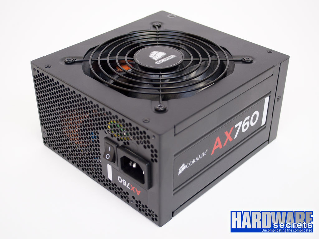 Figure 1: Corsair AX760 power supply
 Figure 2: Corsair AX760 power supply
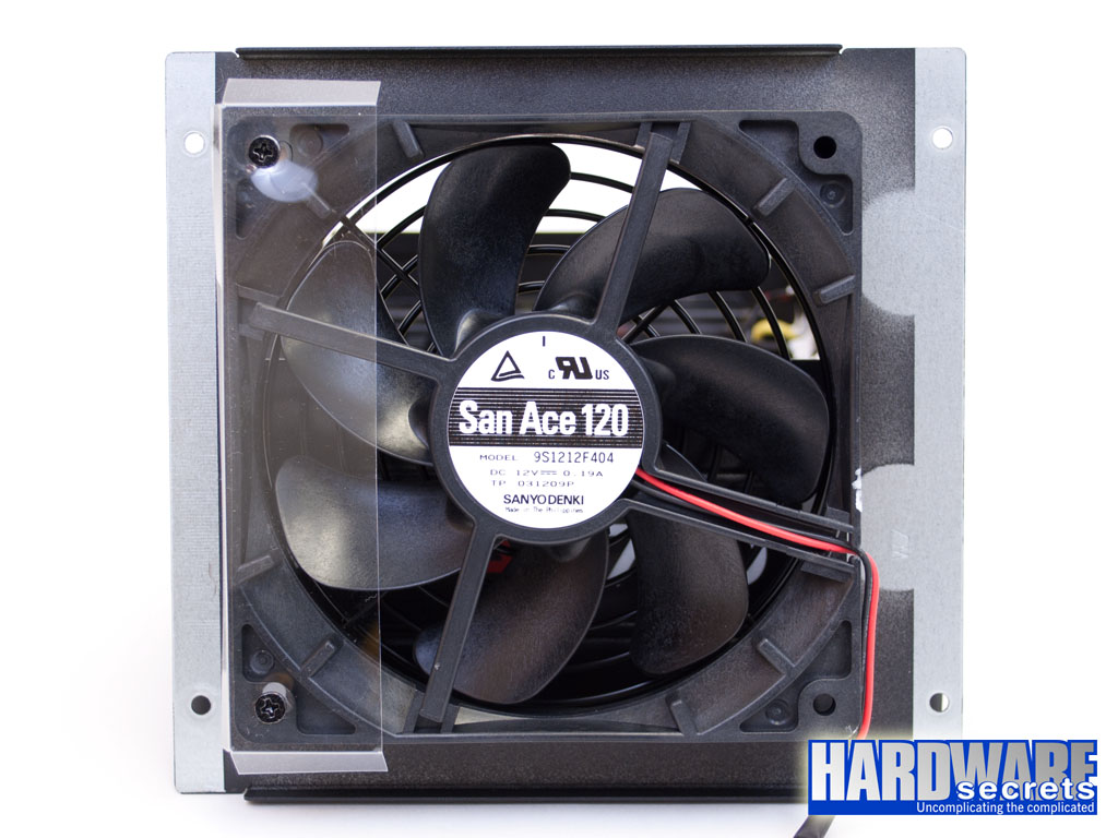
The Corsair AX760 is 6.3” (160 mm) deep. It uses a 120 mm ball-bearing fan on its bottom (Sanyo Denki San Ace 120 9S1212F404). This fan is different from the one used on the Corsair AX760i. The power supply has a “hybrid/normal” switch that allows you to configure the fan to turn on only when the power supply load reaches 70% of the unit’s labeled wattage (i.e., 532 W), so the power supply won’t make any noise when the computer doesn’t demand a lot of power.
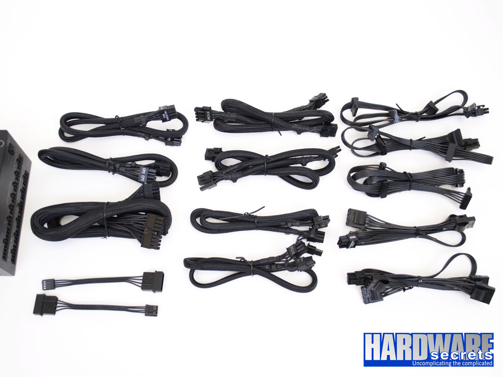
The modular cabling system from this power supply has 13 connectors: two for the main motherboard power connector, six for video card and ATX12V/EPS12V connectors, and five for peripheral and SATA connectors. This power supply comes with the following cables:
- Main motherboard cable with a 20/24-pin connector, 23.6” (60 cm) long
- Two cables, each with two ATX12V connectors that together form an EPS12V connector, 24.8” (63 cm) long
- Two cables, each with two six/eight-pin connectors for video cards, 23.6” (60 cm) to the first connector, 5.9” (15 cm) between connectors
- Two cables, each with one six/eight-pin connector for video cards, 23.6” (60 cm) long
- Two cables, each with four SATA power connectors, 15.7” (40 cm) to the first connector, 3.9” (10 cm) between connectors
- One cable with four SATA power connectors, 21.3” (54 cm) to the first connector, 3.9” (10 cm) between connectors
- Two cables, each with four peripheral power connectors, 17.7” (45 cm) to the first connector, 3.9” (10 cm) between connectors
- Two adapters to convert a standard peripheral power connector into a floppy disk drive power connector
This is the same configuration available on the AX760i model.
All wires are 18 AWG, which is the minimum recommended gauge.
The number of connectors is outstanding for a 760 W power supply, allowing you to install up to three high-end video cards that require two auxiliary power connectors each. The number of SATA power connectors (12) is also impressive.
A Look Inside the Corsair AX760
We decided to disassemble this power supply to see what it looks like inside, how it is designed, and what components are used. Please read our “Anatomy of Switching Power Supplies” tutorial to understand how a power supply works and to compare this power supply to others.
On this page we will have an overall look, and then in the following pages we will discuss in detail the quality and ratings of the components used.
 Figure 8: The printed circuit board
Transient Filtering Stage
As we have mentioned in other articles and reviews, the first place we look when opening a power supply for a hint about its quality, is its filtering stage. The recommended components for this stage are two ferrite coils, two ceramic capacitors (Y capacitors, usually blue), one metalized polyester capacitor (X capacitor), and one MOV (Metal-Oxide Varistor). Very low-end power supplies use fewer components, usually removing the MOV and the first coil.
In the transient filtering stage, this power supply is flawless.
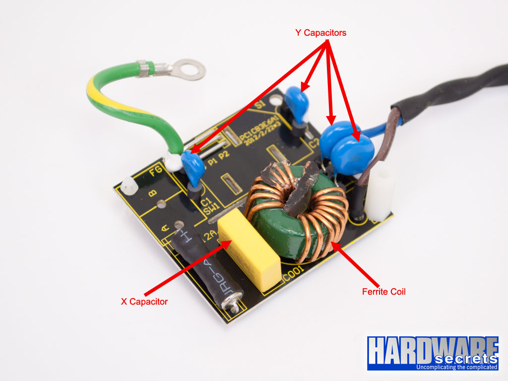 Figure 9: Transient filtering stage (part 1)
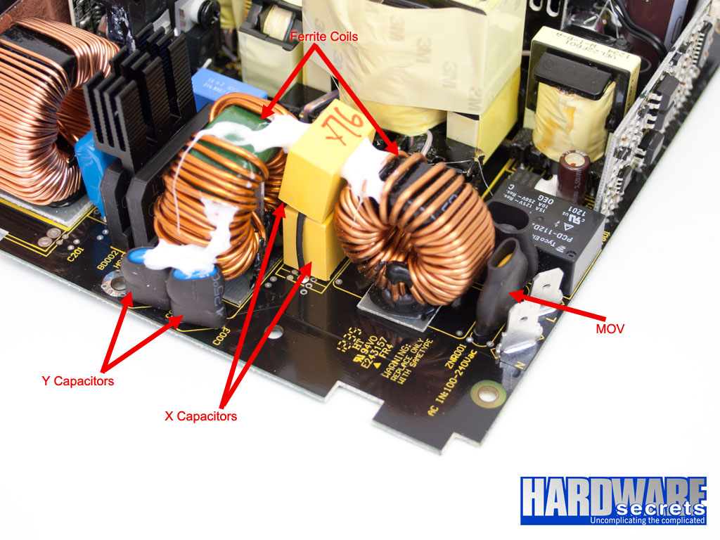 Figure 10: Transient filtering stage (part 2)
Primary Analysis
On this page, we will take an in-depth look at the primary stage of the Corsair AX760. For a better understanding, please read our “Anatomy of Switching Power Supplies” tutorial.
This power supply uses two GBJ1506 rectifying bridges, which are attached to an individual heatsink. Each bridge supports up to 15 A at 100° C. In theory, you would be able to pull up to 3,450 W from a 115 V power grid. Assuming 80% efficiency, the bridges would allow this unit to deliver up to 2,760 W without burning themselves out (or 3,105 W at 90% efficiency). Of course, we are only talking about these particular components. The real limit will depend on all the components combined in this power supply. The AX760i version uses a single 25 A bridge here.
The active PFC circuit uses two IPP60R199CP MOSFETs, each one supporting up to 16 A at 25° C or 10 A at 100° C in continuous mode (note the difference temperature makes), or 51 A at 25° C in pulse mode. These transistors present a 199 mΩ maximum resistance when turned on, a characteristic called RDS(on). The lower the number the better, meaning that the transistor will waste less power, and the power supply will have a higher efficiency. These are the same components used on the AX760i.
 Figure 12: The active PFC diode and transistors
The active PFC circuit is controlled by an NCP1654 integrated circuit. On the AX760i, the active PFC circuit is controlled by the digital signal processor.
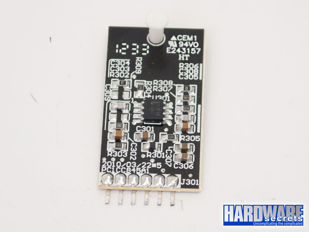 Figure 13: Active PFC controller
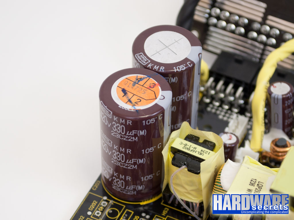
The output of the active PFC circuit is filtered by two 330 μF x 420 V Japanese electrolytic capacitors, from Chemi-Con, labeled at 105° C. These capacitors are connected in parallel and are the equivalent of a single 660 μF x 420 V capacitor. The AX760i uses a single 560 µF x 420 V capacitor here.
In the switching section, four IPP50R250CP MOSFETs are employed using a full-bridge, resonant configuration. Each transistor supports up to 13 A at 25° C or 9 A at 100° C in continuous mode or up to 31 A at 25° C in pulse mode, with a maximum RDS(on) of 250 mΩ. The AX760i uses a different configuration, with only two stronger transistors.
 Figure 15: The switching transistors
The switching transistors are controlled by a CM6901 resonant controller, which is physically located on the same printed circuit board as the +12 V transistors. On the AX760i, the switching transistors are controller by the digital signal processor.
 Figure 16: Resonant controller
Secondary Analysis
As one would expect in a high-efficiency power supply, the Corsair AX760 uses a synchronous design, where the Schottky rectifiers are replaced with MOSFETs. Also, the reviewed product uses a DC-DC design in its secondary. This means that the power supply is basically a +12 V unit, with the +5 V and +3.3 V outputs produced by two smaller power supplies connected to the main +12 V rail. Both designs are used to increase efficiency.
The +12 V output uses four PSMN2R6-40YS MOSFETs, each one supporting up to 100 A at 100° C in continuous mode, or up to 651 A at 25° C in pulse mode, with a maximum RDS(on) of 3.7 mΩ.
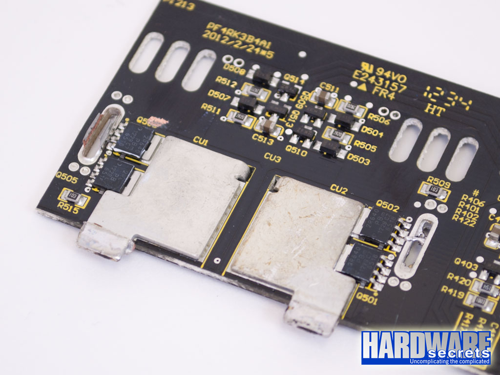 Figure 17: The +12 V transistors
As explained, the +5 V and +3.3 V outputs are produced by two DC-DC converters, which are located on the same printed circuit board as the modular cabling system. This is a different configuration than the one used on the AX760i, which has two separate daughterboards, one for each output. The two converters are controlled by the same PWM controller, an APW7159, and each exit makes use of three BSC0906NS MOSFETs, each one supporting up to 63 A at 25° C or 50 A at 100° C in continuous mode and up to 252 A at 25° C in pulse mode, with a maximum RDS(on) of 4.5 mΩ.
 Figure 18: The DC-DC converters
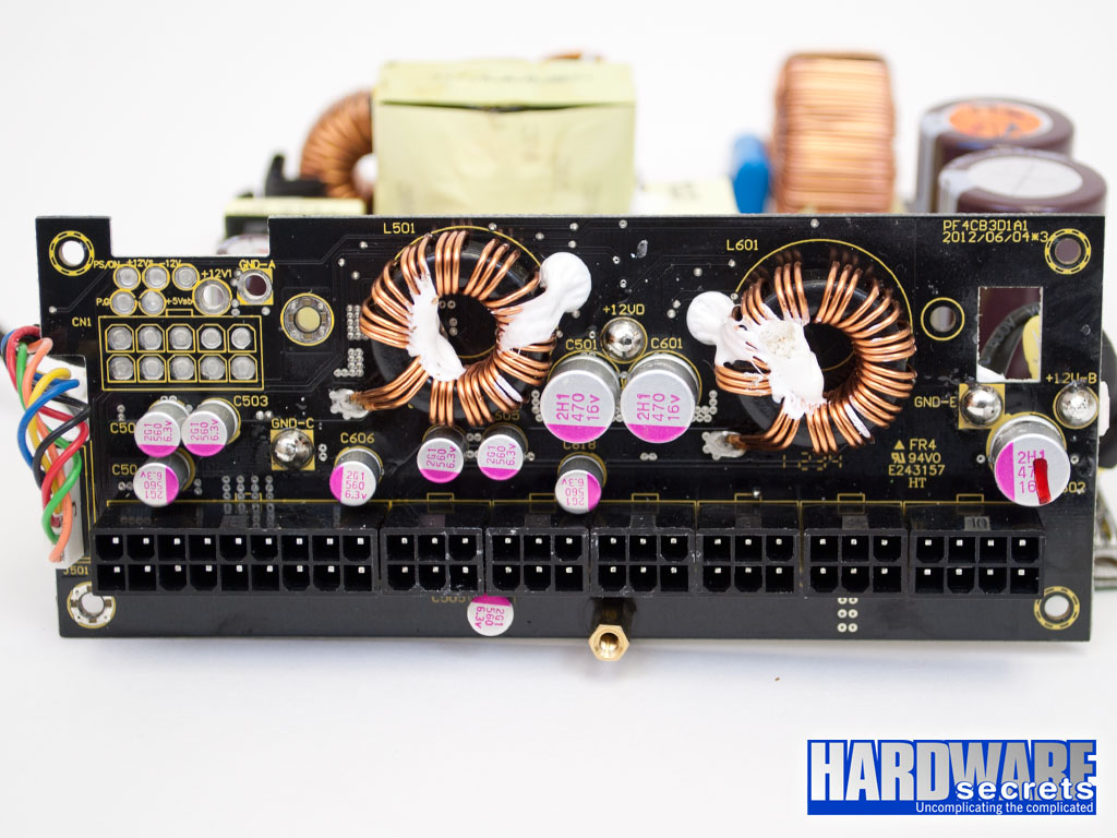 Figure 19: The DC-DC converters
The outputs of the power supply are monitored by a WT7527 integrated circuit, which supports over voltage (OVP), under voltage (UVP), and over current (OCP) protections. There are four OCP channels, one for +3.3 V, one for +5 V, and two for +12 V. The manufacturer, however, decided to use only one of the +12 V channels available, resulting in this unit having a single +12 V rail.
This power supply uses a mix of solid and electrolytic capacitors in its secondary. The electrolytic capacitors are also Japanese, from Chemi-Con, and labeled at 105° C, as usual.
The +5VSB Power Supply
The +5VSB (a.k.a. standby) power supply is independent of the main power supply, since it is on continuously.
On the AX760i, this power supply is located on a separate printed circuit board, whereas on the AX760 this circuit is located on the main printed circuit board.
The +5VSB power supply uses an ICE2QR4765 integrated circuit, which incorporates the PWM controller and the switching transistor into a single chip.
 Figure 22: The +5VSB integrated circuit with an integrated switching transistor
The rectification of the +5VSB output is performed by a PFR30L50CT Schottky rectifier, which supports up to 30 A (15 A per internal diode at 125° C, 0.54 V maximum voltage drop).
 Figure 23: The +5VSB rectifier
Power Distribution
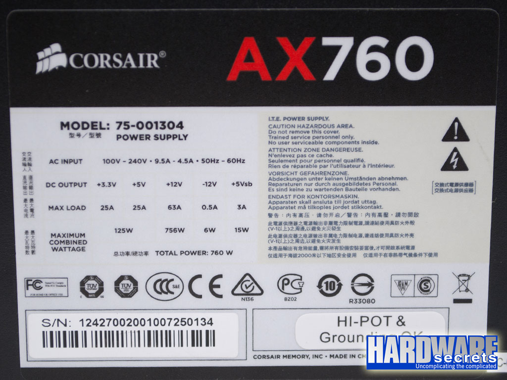
In Figure 24, you can see the power supply label containing all the power specs.
As you can see, this unit has a single +12 V rail configuration.
Load Tests
We conducted several tests with this power supply, as described in the article, “Hardware Secrets Power Supply Test Methodology.”
First, we tested this power supply with five different load patterns, trying to pull around 20%, 40%, 60%, 80%, and 100% of its labeled maximum capacity (actual percentage used listed under “% Max Load”), watching the behavior of the reviewed unit under each load. In the table below, we list the load patterns we used and the results for each load.
If you add all the powers listed for each test, you may find a different value than what is posted under “Total” below. Since each output can have a slight variation (e.g., the +5 V output working at 5.10 V), the actual total amount of power being delivered is slightly different than the calculated value. In the “Total” row, we are using the real amount of power being delivered, as measured by our load tester.
The +12VA and +12VB inputs listed below are the two +12 V independent inputs from our load tester. During this test, the +12VA and +12VB inputs were connected to the power supply’s single +12 V rail. (The +12VB input was connected to the power supply EPS12V connector.)
| Input | Test 1 | Test 2 | Test 3 | Test 4 | Test 5 |
| +12VA | 5.5 A (66 W) | 11.5 A (138 W) | 17 A (204 W) | 22.5 A (270 W) | 28 A (336 W) |
| +12VB | 5.5 A (66 W) | 11 A (132 W) | 16.5 A (198 W) | 22 A (264 W) | 28 A (336 W) |
| +5 V | 1 A (5 W) | 2 A (10 W) | 4 A (20 W) | 6 A (30 W) | 8 A (40 W) |
| +3.3 V | 1 A (3.3 W) | 2 A (6.6 W) | 4 A (13.2 W) | 6 A (19.8 W) | 8 A (26.4 W) |
| +5VSB | 1 A (5 W) | 1.5 A (7.5 W) | 2 A (10 W) | 2.5 A (12.5 W) | 3 A (15 W) |
| -12 V | 0.5 A (6 W) | 0.5 A (6 W) | 0.5 A (6 W) | 0.5 A (6 W) | 0.5 A (6 W) |
| Total | 149.4 W | 298.4 W | 449.4 W | 600.8 W | 758.4 W |
| % Max Load | 19.7% | 39.3% | 59.1% | 79.1% | 99.8% |
| Room Temp. | 46.6° C | 45.1° C | 46.5° C | 49.3° C | 45.4° C |
| PSU Temp. | 48.8° C | 49.0° C | 50.4° C | 53.0° C | 46.0° C |
| Voltage Regulation | Pass | Pass | Pass | Pass | Pass |
| Ripple and Noise | Pass | Pass | Pass | Pass | Pass |
| AC Power | 164.0 W | 324.3 W | 491.6 W | 664.0 W | 850.0 W |
| Efficiency | 91.1% | 92.0% | 91.4% | 90.5% | 89.2% |
| AC Voltage | 117.2 V | 115.6 V | 114.2 V | 112.6 V | 110.4 V |
| Power Factor | 0.993 | 0.988 | 0.993 | 0.995 | 0.996 |
| Final Result | Pass | Pass | Pass | Pass | Pass |
The Corsair AX760 performed correctly according to the 80 Plus Platinum certification, which promises efficiency of at least 90% under light (i.e., 20%) load, 92% under typical (i.e., 50%) load, and 89% under full (i.e., 100%) load.
Voltage Regulation Tests
The ATX12V specification states that positive voltages must be within 5% of their nominal values, and negative voltages must be within 10% of their nominal values. We consider a power supply as “flawless” if it shows voltages within 3% of its nominal values. In the table below, you can see the power supply voltages during our tests and, in the following table, the deviation, in percentage, of their nominal values.
The Corsair AX760 presented outstanding voltage regulation, with all its main positive voltages within 1% of their nominal values.
| Input | Test 1 | Test 2 | Test 3 | Test 4 | Test 5 |
| +12VA | +12.08 V | +12.06 V | +12.04 V | +12.02 V | +11.98 V |
| +12VB | +12.10 V | +12.06 V | +12.03 V | +11.99 V | +11.95 V |
| +5 V | +5.02 V | +5.02 V | +5.01 V | +5.01 V | +5.00 V |
| +3.3 V | +3.33 V | +3.31 V | +3.31 V | +3.30 V | +3.30 V |
| +5VSB | +5.04 V | +5.02 V | +4.98 V | +4.95 V | +4.92 V |
| -12 V | -11.55 V | -11.69 V | -11.84 V | -12.01 V | -12.17 V |
| Input | Test 1 | Test 2 | Test 3 | Test 4 | Test 5 |
| +12VA | 0.67% | 0.50% | 0.33% | 0.17% | -0.17% |
| +12VB | 0.83% | 0.50% | 0.25% | -0.08% | -0.42% |
| +5 V | 0.40% | 0.40% | 0.20% | 0.20% | 0.00% |
| +3.3 V | 0.91% | 0.30% | 0.30% | 0.00% | 0.00% |
| +5VSB | 0.80% | 0.40% | -0.40% | -1.00% | -1.60% |
| -12 V | 3.90% | 2.65% | 1.35% | -0.08% | -1.40% |
Ripple and Noise Tests
Voltages at the power supply outputs must be as “clean” as possible, with no noise or oscillation (also known as “ripple”). The maximum ripple and noise levels allowed are 120 mV for +12 V and -12 V outputs, and 50 mV for +5 V, +3.3 V and +5VSB outputs. All values are peak-to-peak figures. We consider a power supply as being top-notch if it can produce half or less of the maximum allowed ripple and noise levels.
The Corsair AX760 provided extremely low ripple and noise levels, as you can see in the table below.
| Input | Test 1 | Test 2 | Test 3 | Test 4 | Test 5 |
| +12VA | 13.0 mV | 15.4 mV | 17.4 mV | 21.0 mV | 24.2 mV |
| +12VB | 12.8 mV | 16.2 mV | 19.0 mV | 23.4 mV | 28.6 mV |
| +5 V | 10.8 mV | 10.0 mV | 11.2 mV | 12.0 mV | 13.0 mV |
| +3.3 V | 7.8 mV | 8.8 mV | 9.2 mV | 10.8 mV | 12.6 mV |
| +5VSB | 4.8 mV | 6.2 mV | 7.4 mV | 7.0 mV | 8.2 mV |
| -12 V | 11.8 mV | 13.4 mV | 13.6 mV | 14.2 mV | 19.4 mV |
Below you can see the waveforms of the outputs during test five.
 Figure 25: +12VA input from load tester during test five at 758.4 W (24.2 mV)
 Figure 26: +12VB input from load tester during test five at 758.4 W (28.6 mV)
 Figure 27: +5V rail during test five at 758.4 W (13 mV)
 Figure 28: +3.3 V rail during test five at 758.4 W (12.6 mV)
